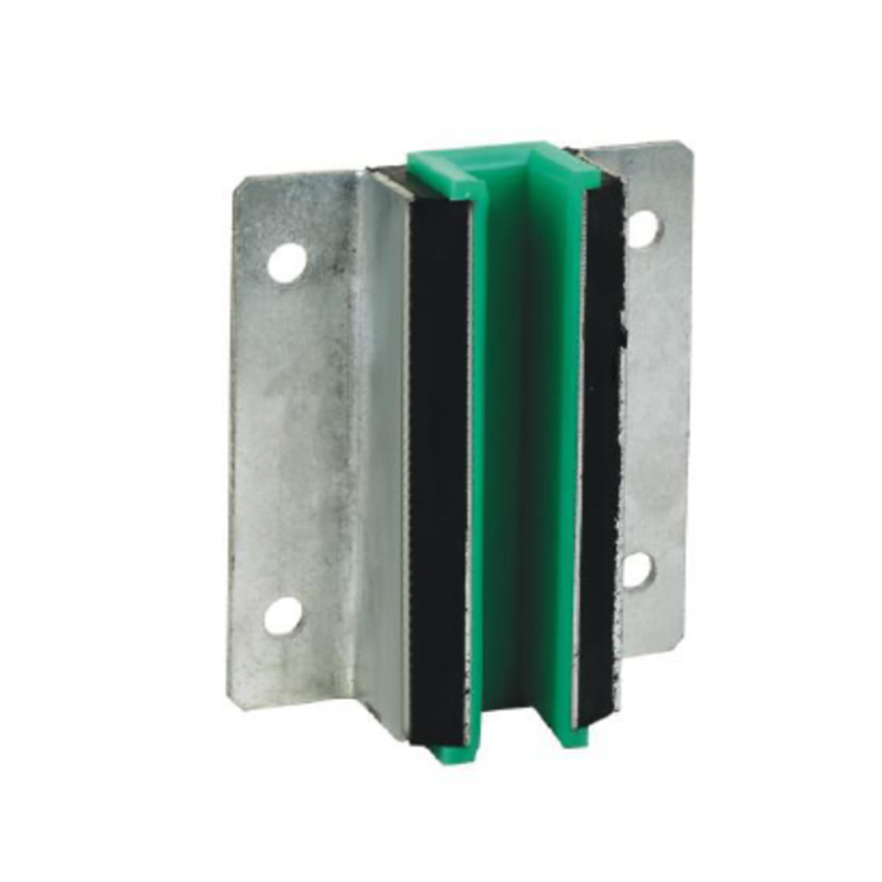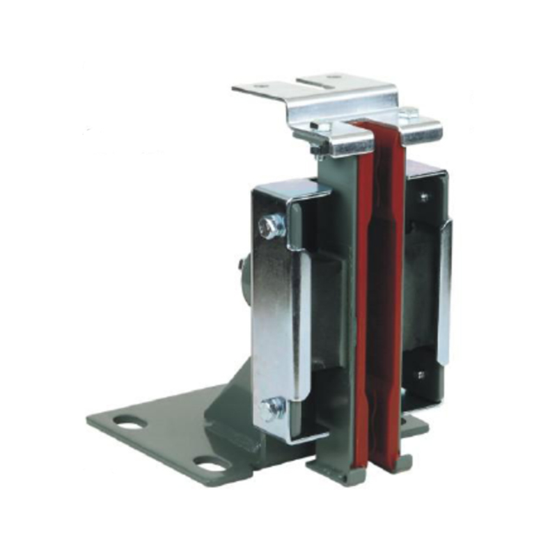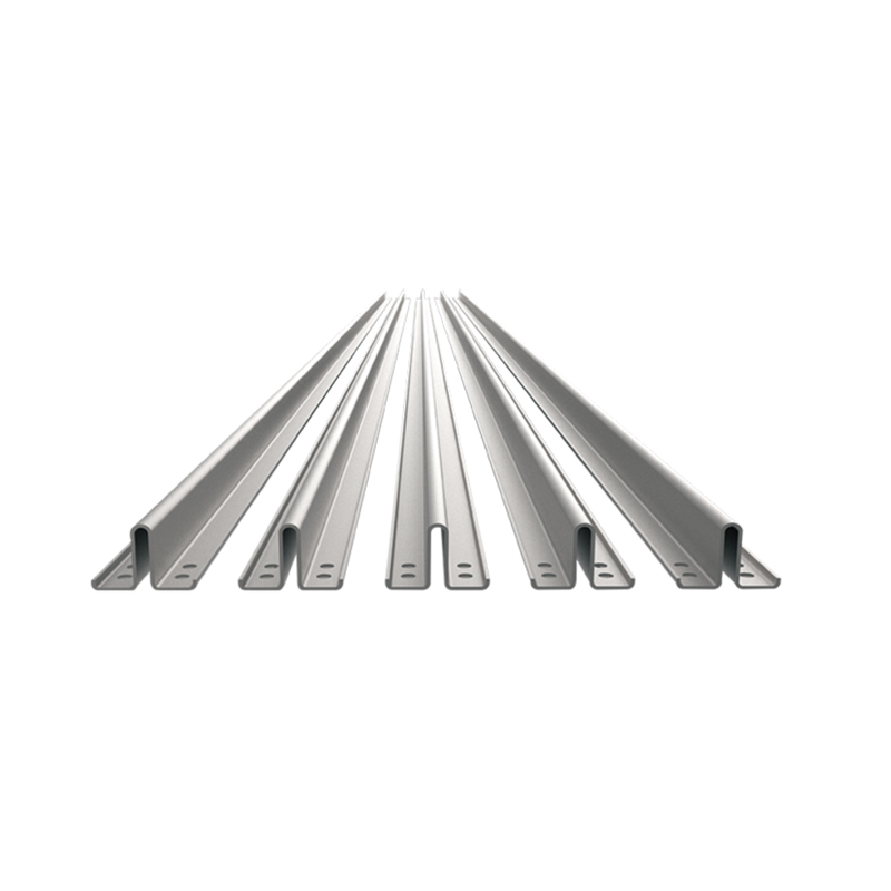


Hollow Rail
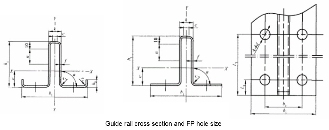
Main dimensions of guide rail
| Main dimensions of guide rail | ||||||||||||||
| L | b1 | c | f | h1 | h2 | k | n | L2 | L3 | d | r1 | a | Standard | |
| Tolerance (mm) | JG/T 5072.3-1996 | |||||||||||||
| Model | ±3 | ±0.4 | ||||||||||||
| TK3 | 5000 | 87±1 | ≥1.8 | 2 | 60 | 16.4 | 25 | 180 | 20 | 14 | 3 | 90° | ||
| TK5 | 3 | |||||||||||||
| TK8 | 100±2 | ≥4 | 4.5 | 80 | 22 | 30 | 200 | 25 | 6 | 90° | ||||
| TK3A | ≥1.8 | 2.2 | 60 | 10±0.1 | 16.4 | 25 | 180 | 25 | 3 | 90° | ||||
| TK5A | 3.2 | |||||||||||||
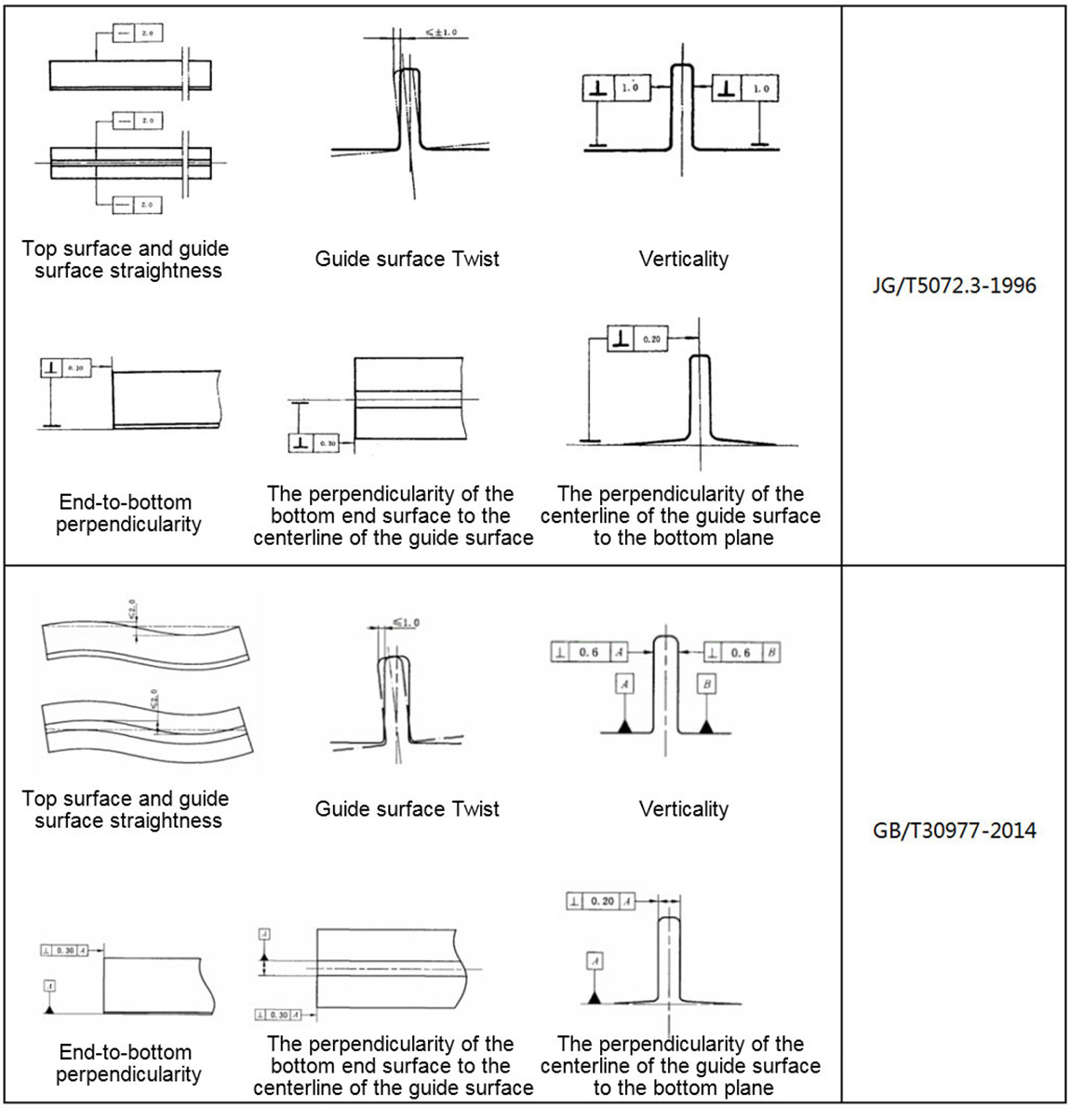
| The top surface and the guide surface within 5mm at both ends of the guide rail are allowed to have a uniform contraction slope of not more than 0.5mm. The straightness of the top surface of the guide rail along the length of the guide rail should not be greater than 2.0mm. (See Figure 3 for details) |
||||||||||||||
| Tolerance (mm) | GB/T 30977-2014 | |||||||||||||
| Model | ±3 | ±0.4 | ±0.5 | ±0.3 | ||||||||||
| TK3 | 5000 | 87±1 | ≥1.8 | 2 | 60 | 16.4 | 25 | 180 | 20 | 14 | 3 | 90° | ||
| TK5 | 3 | |||||||||||||
| TK8 | 100±2 | ≥4 | 4.5 | 80 | 22 | 30 | 200 | 25 | 6 | 90° | ||||
| TK3A | 78±1 | ≥1.8 | 2.2 | 60 | 10 | 16.4 | 25 | 75 | 25 | 11.5 | 3 | 90° | ||
| TK5A-1 | 3 | |||||||||||||
| TK5A | 3.2 | |||||||||||||
| The top surface and the guide surface within 5mm of the two ends of the guide rail should have a slope of not more than 1:10. Technical requirements: The twist along the length of the guide rail within 5m of the top surface of the guide rail and the guide surface should not be greater than 2.0mm on the guide surfaces on both sides, and should not be greater than 2.0mm on the top guide surface. (See Figure 3 for details) |
||||||||||||||